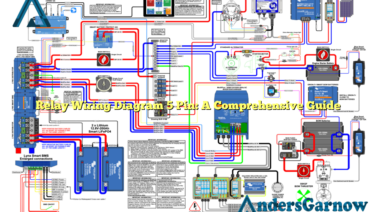
Hello dear readers! In this article, we will delve into the world of relay wiring diagram 5 pin, providing you with a detailed understanding of its functionalities, advantages, and disadvantages. So, let’s get started!
1. What is a Relay Wiring Diagram 5 Pin?
A relay wiring diagram 5 pin is a visual representation of the electrical connections and functions of a 5-pin relay. It illustrates how the various pins of the relay are connected to different components in an electrical circuit.
2. Understanding the Pin Configuration
The 5-pin relay consists of five pins, namely the coil pin, normally open (NO) pin, normally closed (NC) pin, common (COM) pin, and the control pin. The coil pin is used to activate the relay, while the NO and NC pins control the current flow in the circuit.
3. Advantages of Using a Relay Wiring Diagram 5 Pin
There are several advantages to using a relay wiring diagram 5 pin:
- Flexibility: The 5-pin relay allows for versatile wiring configurations, making it suitable for various electrical applications.
- Reliability: Relays provide a reliable way to control high-current circuits without directly switching the load.
- Easy Troubleshooting: A well-labeled relay wiring diagram simplifies troubleshooting and maintenance tasks.
- Space Saving: The compact size of the 5-pin relay makes it ideal for installations where space is limited.
4. Disadvantages of Using a Relay Wiring Diagram 5 Pin
Despite its advantages, the 5-pin relay also has some limitations:
- Complexity: Understanding and correctly wiring a relay can be challenging for individuals without a solid understanding of electrical circuits.
- Cost: Relays can be more expensive compared to direct wiring solutions for low-current applications.
5. Alternative Relay Wiring Diagrams
While the 5-pin relay is widely used, there are alternative wiring diagrams available:
- 4-Pin Relay Wiring Diagram: Similar to the 5-pin relay, but without the NC pin.
- 3-Pin Relay Wiring Diagram: Used for simpler circuits, featuring only the coil, COM, and NO pins.
6. Relay Wiring Diagram 5 Pin – Detailed Breakdown
To provide you with a detailed understanding, let’s break down the functionality of each pin in a relay wiring diagram 5 pin:
| Pin | Symbol | Description |
|---|---|---|
| Coil |  Source: None Source: None |
Used to activate the relay by applying an electrical current. |
| NO |  Source: None Source: None |
Normally Open pin that connects to the load and allows current flow when the relay is activated. |
| NC |  Source: None Source: None |
Normally Closed pin that disconnects from the load when the relay is activated. |
| COM |  Source: None Source: None |
Common pin that acts as a bridge between the NO and NC pins. |
| Control |  Source: None Source: None |
Controls the activation of the relay by providing or cutting off the electrical current to the coil. |
7. Frequently Asked Questions (FAQ) about Relay Wiring Diagram 5 Pin
Q: Can I use a 5-pin relay for low-current applications?
A: Yes, the 5-pin relay can handle both low and high-current applications, providing flexibility in various electrical setups.
Q: How do I determine the correct wiring connections for a specific circuit?
A: It is essential to consult the datasheet or manufacturer’s instructions for the relay you are using. They will provide the necessary information and pin assignments.
Conclusion
In conclusion, a relay wiring diagram 5 pin is a valuable tool for understanding and implementing electrical circuits involving relays. It offers flexibility, reliability, and easy troubleshooting, while also having some complexity and cost considerations. By following the pin configuration and understanding its functionality, you can effectively utilize the 5-pin relay in various applications. Remember to consult the datasheet and manufacturer’s instructions for specific wiring requirements. Happy wiring!

