Hello readers! In this article, we will discuss the wiring diagram for a single phase 480 to 120/240 transformer. This diagram is crucial for understanding how to properly connect and operate the transformer for various electrical applications. So, let’s dive into the details!
1. Introduction to Single Phase 480 to 120/240 Transformer
A single phase 480 to 120/240 transformer is a type of electrical transformer that converts the voltage from 480 volts to two different levels: 120 volts and 240 volts. It is commonly used in residential, commercial, and industrial settings to power various appliances and equipment.
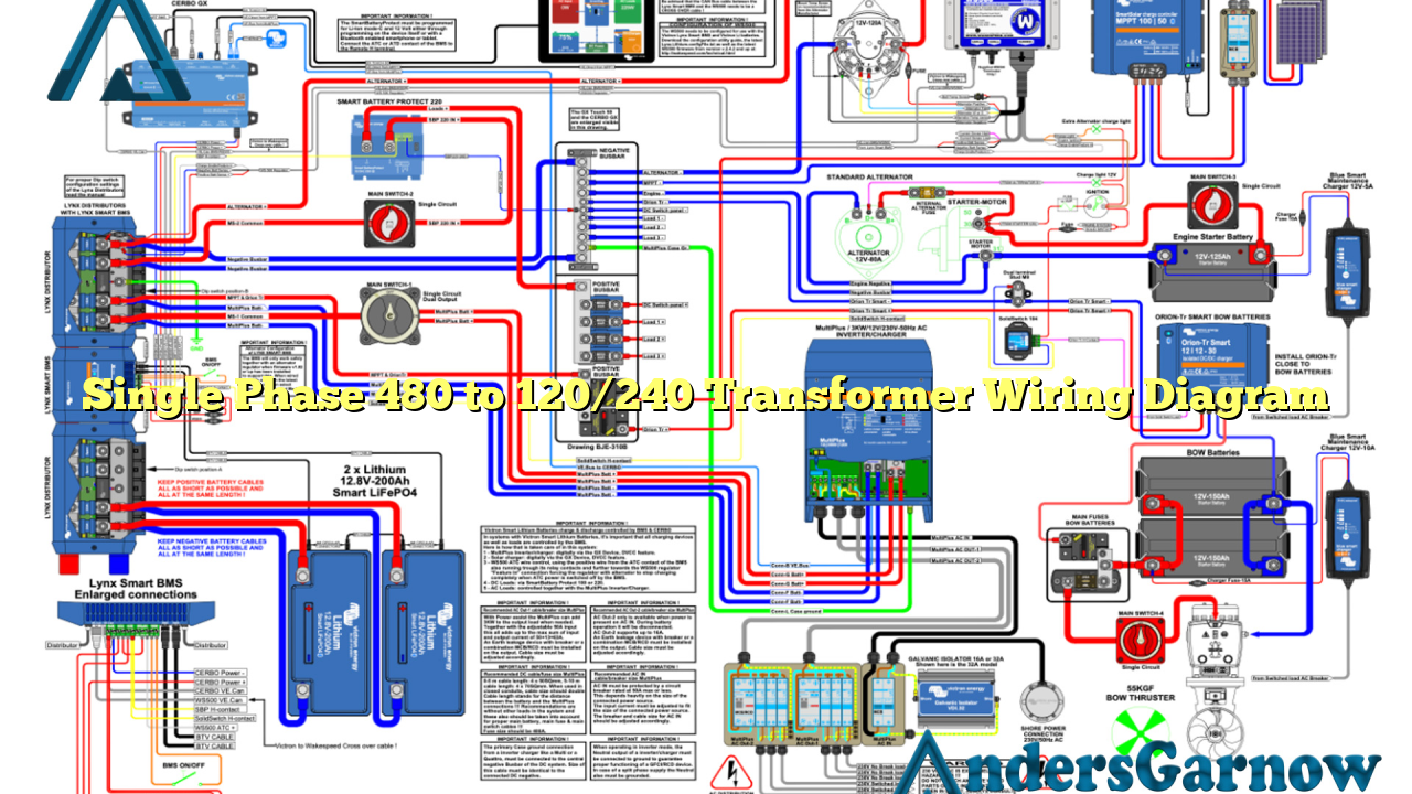
2. Wiring Diagram for Single Phase 480 to 120/240 Transformer
To understand the wiring diagram, let’s break it down step by step:
Step 1: Begin by identifying the primary and secondary winding terminals on the transformer. The primary winding is the side that receives the 480-volt input, while the secondary winding provides the 120/240-volt output.
Step 2: Connect one of the primary winding terminals to L1 of the electrical supply, and the other primary terminal to L2. These two terminals will receive the 480-volt input.
Step 3: Connect a jumper wire from L1 to L3, and another jumper wire from L2 to L3. This creates a delta configuration for the primary winding.
Step 4: Connect the primary winding to the electrical supply ground, often referred to as the earth ground.
Step 5: Moving on to the secondary winding, connect one of the secondary terminals to X1, and the other secondary terminal to X2. These terminals will provide the 240-volt output.
Step 6: Connect a jumper wire from X1 to X3, and another jumper wire from X2 to X3. This creates a center-tapped configuration for the secondary winding, allowing for the 120-volt output.
Step 7: Connect the X3 terminal to the electrical supply neutral.
Once the wiring connections are made according to the diagram, the single phase 480 to 120/240 transformer is ready to be used for its intended purposes.
3. Advantages of Single Phase 480 to 120/240 Transformer Wiring Diagram
The wiring diagram for a single phase 480 to 120/240 transformer offers several advantages:
Efficient Power Distribution: By converting the voltage from 480 volts to 120/240 volts, the transformer enables efficient power distribution to various appliances and equipment.
Flexibility: The dual voltage outputs of 120 volts and 240 volts provide flexibility in accommodating different electrical devices and their power requirements.
Safe Operation: Following the wiring diagram ensures safe and reliable operation of the transformer, minimizing the risk of electrical hazards.
4. Disadvantages of Single Phase 480 to 120/240 Transformer Wiring Diagram
While the wiring diagram offers numerous advantages, it is essential to consider some potential disadvantages:
Complexity: The wiring process may be complex for individuals without sufficient electrical knowledge and experience. It is recommended to seek professional assistance when dealing with such electrical installations.
Space Requirements: The transformer and associated wiring may require significant space, especially in applications where multiple transformers are used.
5. Alternative Wiring Options for Single Phase 480 to 120/240 Transformer
In addition to the discussed wiring diagram, there are alternative options available to connect the single phase 480 to 120/240 transformer:
Buck-Boost Transformer: A buck-boost transformer can be used to achieve the desired voltage conversion. It provides a simpler wiring arrangement compared to the conventional transformer.
Smart Transformer: Smart transformers with advanced control features offer more flexibility and efficiency in voltage conversion. They can be programmed and remotely controlled to adapt to varying power demands.
6. Single Phase 480 to 120/240 Transformer Wiring Diagram Table
| Terminal | Connection |
|---|---|
| Primary Terminal 1 | Connected to L1 of the electrical supply |
| Primary Terminal 2 | Connected to L2 of the electrical supply |
| Primary Terminal 1 | Jumper wire connected to L3 of the electrical supply |
| Primary Terminal 2 | Jumper wire connected to L3 of the electrical supply |
| Primary Terminal 1 and 2 | Connected to electrical supply ground |
| Secondary Terminal 1 | Connected to X1 |
| Secondary Terminal 2 | Connected to X2 |
| Secondary Terminal 1 | Jumper wire connected to X3 |
| Secondary Terminal 2 | Jumper wire connected to X3 |
| X3 | Connected to electrical supply neutral |
7. Frequently Asked Questions (FAQ) – Single Phase 480 to 120/240 Transformer Wiring Diagram
Q: Can I connect multiple appliances to the transformer’s secondary output?
A: Yes, the 120/240-volt output terminals can be used to power multiple appliances simultaneously. However, it is essential to consider the total power consumption and ensure it does not exceed the transformer’s rated capacity.
Q: Can I use a single phase 480 to 120/240 transformer for three-phase applications?
A: No, a single phase transformer is designed for single-phase applications only. For three-phase applications, a three-phase transformer should be used.
Q: Is it necessary to ground the transformer?
A: Yes, grounding the transformer is crucial for safety reasons. It helps protect against electrical faults and ensures proper functioning of the electrical system.
Conclusion
In conclusion, the single phase 480 to 120/240 transformer wiring diagram provides a comprehensive guide for connecting and operating the transformer. By following the diagram and understanding the connections, users can ensure safe and efficient power distribution for various electrical applications. Remember to always prioritize safety and consult professionals when needed. Now, you are equipped with the knowledge to handle single phase transformer wiring effectively!

