Hello readers, welcome to this informative article about schematics. In this piece, we will explore the concept of schematics, its advantages, disadvantages, and alternative options. So, let’s dive in and learn more about schematics!
1. Understanding Schematics
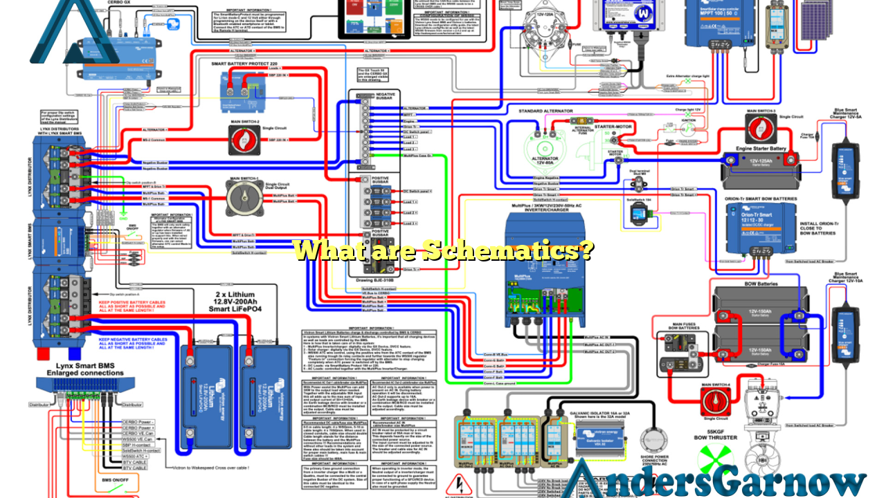
Schematics, also known as circuit diagrams or electrical diagrams, are graphical representations of an electrical circuit. They illustrate the connections between different components and their relationship to each other within a circuit. Schematics use standardized symbols to depict various electrical components such as resistors, capacitors, transistors, and more.
2. The Purpose of Schematics
The primary purpose of schematics is to provide a visual representation of an electrical circuit. They help engineers, electricians, and technicians understand how a circuit works, troubleshoot issues, design new systems, and make modifications to existing ones. Schematics act as a blueprint for building and understanding complex electrical systems.
3. Advantages of Schematics
Schematics offer several advantages:
- Clarity: Schematics provide a clear and concise representation of an electrical circuit, making it easier to understand and analyze.
- Troubleshooting: Schematics assist in identifying and resolving issues within a circuit by visually tracing the connections and components.
- Design and Modification: Schematics are crucial for designing new circuits and making modifications to existing ones, ensuring accuracy and efficiency.
- Documentation: Schematics serve as valuable documentation for future reference, maintenance, and repairs.
4. Disadvantages of Schematics
While schematics offer numerous benefits, they also have some limitations:
- Complexity: Schematics can become complex and challenging to understand, especially for more intricate circuits.
- Learning Curve: Reading and interpreting schematics require some level of knowledge and experience in electrical circuits.
- Space Constraints: Large and complex circuits may require significant space to fit all the components and connections, making schematics bulky.
5. Alternative Options
Although schematics are widely used, alternative options exist for representing electrical circuits:
- Block Diagrams: Block diagrams provide a higher-level view of a system, focusing on the interconnections between functional blocks rather than individual components.
- Breadboard Diagrams: Breadboard diagrams are physical representations of circuits using breadboards, allowing for quick prototyping and experimentation.
- PCB Layouts: PCB (Printed Circuit Board) layouts depict the physical arrangement of components on a circuit board, including their connections and traces.
6. Schematics Table
| Information | Description |
|---|---|
| Definition | A graphical representation of an electrical circuit using standardized symbols. |
| Purpose | To understand, design, troubleshoot, and modify electrical circuits. |
| Advantages | Clarity, troubleshooting assistance, design and modification capabilities, documentation. |
| Disadvantages | Complexity, learning curve, space constraints. |
| Alternative Options | Block diagrams, breadboard diagrams, PCB layouts. |
7. Frequently Asked Questions (FAQ)
Q: How can I learn to read and interpret schematics?
A: There are various resources available, such as online tutorials, books, and courses that can help you learn the basics of reading and interpreting schematics.
Q: Are there any software tools available for creating schematics?
A: Yes, there are several software tools available, both free and paid, that assist in creating professional-looking schematics with ease. Some popular options include Eagle, KiCad, and Altium Designer.
Q: Can schematics be used for digital circuits as well?
A: Yes, schematics can be used for both analog and digital circuits. However, digital circuits often utilize additional notations and symbols specific to digital logic.
In Conclusion
In conclusion, schematics are essential tools for understanding, designing, and troubleshooting electrical circuits. They offer clarity, aid in troubleshooting, and serve as valuable documentation. While they have some limitations, alternative options like block diagrams, breadboard diagrams, and PCB layouts provide flexibility in circuit representation. By mastering the art of reading and interpreting schematics, you can unlock a world of possibilities in the field of electronics.
