Hello readers! In this article, we will explore the wiring diagram for a 3 wire alternator. Understanding the wiring diagram is essential for proper installation and troubleshooting of the alternator system in your vehicle. So, let’s dive into the details!
1. Introduction to the 3 Wire Alternator
A 3 wire alternator is a type of alternator commonly used in automotive applications. It consists of three main connections – a battery terminal, an ignition switch terminal, and a voltage sensing terminal. These connections allow the alternator to generate electricity and charge the vehicle’s battery.
2. Wiring Connections
The wiring connections for a 3 wire alternator are relatively simple. The battery terminal is connected directly to the positive terminal of the vehicle’s battery. The ignition switch terminal is connected to the ignition switch, which controls the alternator’s operation. Finally, the voltage sensing terminal is connected to the vehicle’s electrical system, allowing the alternator to sense the battery’s voltage and adjust its output accordingly.
3. Benefits of a 3 Wire Alternator
One of the main benefits of a 3 wire alternator is its simplicity. The wiring connections are straightforward, making it easier to install and troubleshoot. Additionally, the voltage sensing terminal ensures that the alternator provides the correct charging voltage, preventing overcharging or undercharging of the battery.
4. Limitations of a 3 Wire Alternator
Despite its simplicity, a 3 wire alternator has some limitations. Firstly, it may not be suitable for high-power applications, as it has a limited output capacity. Secondly, the voltage sensing terminal relies on the vehicle’s electrical system, which may introduce inaccuracies in voltage sensing. Finally, the wiring connections may vary depending on the vehicle’s make and model, so it’s important to consult the specific wiring diagram for your vehicle.
5. Wiring Diagram Alternatives
If the wiring diagram for a 3 wire alternator doesn’t suit your specific needs, there are alternative options available. One common alternative is a single-wire alternator, which eliminates the need for the voltage sensing terminal. However, the single-wire alternator may not provide the same level of accuracy in voltage sensing as the 3 wire alternator.
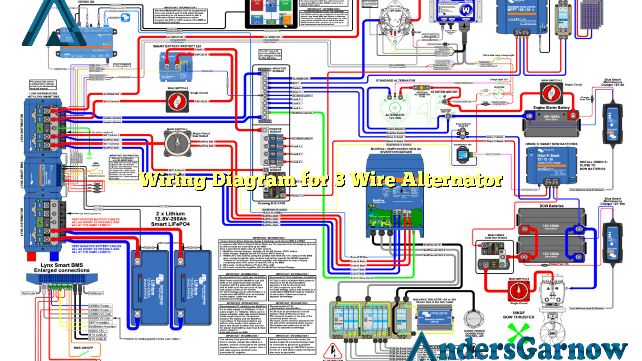
6. Wiring Diagram for 3 Wire Alternator – Step by Step
Below is a detailed step-by-step guide on how to wire a 3 wire alternator:
| Wire Color | Connection |
|---|---|
| Red | Battery Terminal – Connect to the positive terminal of the vehicle’s battery using a suitable gauge wire. |
| White | Ignition Switch Terminal – Connect to the ignition switch using a suitable gauge wire. |
| Black | Voltage Sensing Terminal – Connect to the vehicle’s electrical system using a suitable gauge wire. |
7. FAQ (Frequently Asked Questions)
Q: Can I use a 3 wire alternator in my high-performance vehicle?
A: While a 3 wire alternator is suitable for most applications, high-performance vehicles may require an alternator with a higher output capacity.
Q: What gauge wire should I use for the wiring connections?
A: The gauge of the wire will depend on the specific requirements of your vehicle. Consult the manufacturer’s guidelines or a professional for the appropriate wire gauge.
Conclusion
In conclusion, understanding the wiring diagram for a 3 wire alternator is essential for proper installation and troubleshooting. While it offers simplicity and accurate voltage sensing, it may not be suitable for high-power applications. Consult the specific wiring diagram for your vehicle and consider alternative options if necessary. Proper wiring and connections will ensure the efficient operation of your alternator system and help maintain your vehicle’s electrical system.
