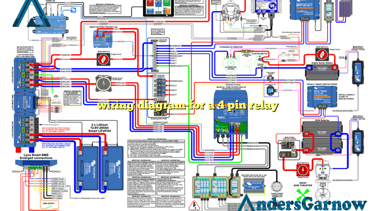
Hello readers! In this article, we will be discussing the wiring diagram for a 4 pin relay. A relay is an electrical device that allows a low-power signal to control a high-power circuit. Understanding the wiring diagram of a 4 pin relay is essential for proper installation and usage. So, let’s dive into the details!
1. What is a 4 pin relay?
A 4 pin relay consists of four terminals or pins – two control pins and two power pins. The control pins are used to connect the relay to a control circuit, while the power pins are used to connect the relay to the power source and the load. It acts as a switch that can be controlled by a small electrical signal.
2. Pin configuration
The pin configuration of a 4 pin relay is as follows:
| Pin Number | Description |
|---|---|
| Pin 1 | Control Pin 1 (Positive) |
| Pin 2 | Control Pin 2 (Negative) |
| Pin 3 | Power Pin 1 (Positive) |
| Pin 4 | Power Pin 2 (Negative) |
3. Wiring connections
When wiring a 4 pin relay, it is important to make the correct connections. The control pins are connected to the control circuit, which can be a switch or an electronic control unit. The power pins are connected to the power source and the load. It is crucial to ensure that the polarities are correct to prevent any damage to the relay or the connected devices.
4. Advantages of using a 4 pin relay
There are several advantages of using a 4 pin relay:
- Easy to install and use.
- Provides reliable switching for high-power circuits.
- Allows control of multiple devices using a single control signal.
- Protects the control circuit from high currents.
5. Disadvantages of using a 4 pin relay
While a 4 pin relay has its advantages, it also has some limitations:
- Limited control options compared to more complex relays.
- Cannot handle extremely high currents.
- May produce electrical noise during switching.
6. Alternative wiring diagram
Another wiring diagram option for a 4 pin relay is to connect the control pins in parallel. This allows multiple control signals to activate the relay simultaneously. However, it is crucial to ensure that the total current does not exceed the relay’s maximum capacity.
FAQs
Q: Can I use a 4 pin relay for automotive applications?
A: Yes, 4 pin relays are commonly used in automotive applications for controlling various electrical devices such as headlights, horns, and fans.
Q: How do I test a 4 pin relay?
A: To test a 4 pin relay, you can use a multimeter to check for continuity between the power pins when the control pins are activated. You can also listen for a clicking sound, indicating that the relay is switching.
Conclusion
In conclusion, understanding the wiring diagram for a 4 pin relay is crucial for proper installation and usage. It allows you to control high-power circuits using a low-power signal. Remember to make the correct connections and consider the advantages and disadvantages before using a 4 pin relay. Stay safe and happy wiring!

