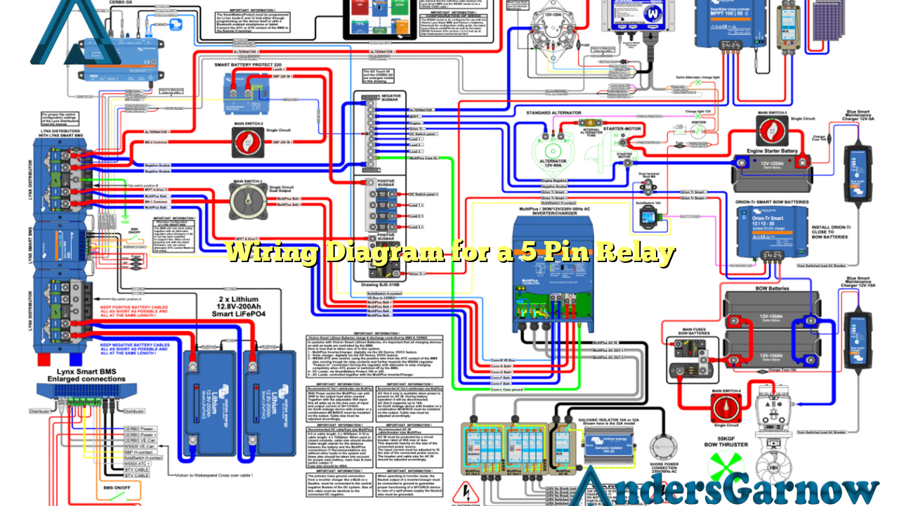
Hello readers! In this article, we will discuss the wiring diagram for a 5 pin relay. A relay is an electrical device that allows a low-power signal to control a high-power circuit. It is commonly used in automotive applications to control various electrical components such as lights, motors, and fans. Understanding the wiring diagram for a 5 pin relay is essential for proper installation and troubleshooting. So, let’s dive into the details!
1. Pin Configuration
The first subtopic we will cover is the pin configuration of a 5 pin relay. A typical 5 pin relay consists of five pins – two for the coil and three for the switch contacts. The pins are labeled as follows:
| Pin | Description |
|---|---|
| Pin 30 | Main power input |
| Pin 85 | Coil ground |
| Pin 86 | Coil positive |
| Pin 87 | Normally open contact |
| Pin 87a | Normally closed contact |
The pin configuration may vary slightly depending on the manufacturer, but the basic functionality remains the same.
2. Wiring Connections
Now, let’s discuss the wiring connections for a 5 pin relay. The coil pins (85 and 86) are connected to a power source and a ground, usually through a switch or control module. Pins 30 and 87 are used to control the high-power circuit. Pin 30 is connected to the power source, while pin 87 is connected to the load (e.g., lights, motors).
When the coil is energized, the switch contacts (pins 87 and 87a) change their state. In the resting state, pin 87a is connected to pin 30 (normally closed contact), and when the coil is energized, pin 87 is connected to pin 30 (normally open contact).
3. Advantages of Using a 5 Pin Relay
Using a 5 pin relay offers several advantages:
- Versatility: A 5 pin relay can be used for various applications due to its multiple switch contacts.
- Reliability: Relays are known for their durability and long lifespan, making them a reliable choice for controlling high-power circuits.
- Easy Installation: The straightforward wiring and pin configuration of a 5 pin relay make it easy to install, even for beginners.
- Protection: Relays provide protection to the control circuit by isolating it from the high-power circuit.
4. Disadvantages of Using a 5 Pin Relay
While a 5 pin relay has its advantages, it also has some limitations:
- Size: Relays can be bulky and take up significant space compared to solid-state devices.
- Power Consumption: The coil of a relay requires power, which adds to the overall power consumption of the circuit.
- Noise: Relays can produce audible clicking sounds when switching, which may be undesirable in certain applications.
5. Alternative Wiring Diagram
Another wiring diagram for a 5 pin relay is the use of a diode across the coil. This diode, called a freewheeling diode or suppression diode, is connected in reverse polarity across the coil (anode to positive, cathode to negative). The diode serves to suppress voltage spikes and protect the control circuit from damage caused by the collapsing magnetic field of the coil.
FAQs (Frequently Asked Questions)
Q: Can I use a 5 pin relay for both AC and DC applications?
A: Yes, a 5 pin relay can be used for both AC and DC applications. However, make sure to choose a relay with suitable voltage and current ratings for your specific application.
Q: How do I test a 5 pin relay?
A: To test a 5 pin relay, you can use a multimeter to check the continuity of the switch contacts and measure the coil resistance. Additionally, you can apply power to the coil and listen for the clicking sound of the switch contacts.
Conclusion
In conclusion, understanding the wiring diagram for a 5 pin relay is crucial for proper installation and troubleshooting in various applications. The pin configuration, wiring connections, advantages, and disadvantages discussed in this article provide a comprehensive overview of this essential electrical component. Whether you are an automotive enthusiast or a DIYer, knowing how to utilize a 5 pin relay can greatly enhance your electrical projects. So, go ahead and apply this knowledge to harness the power of relays in your circuits!

