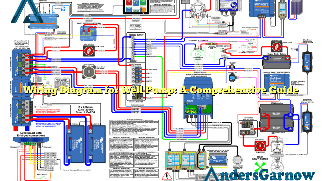
Hello readers! Welcome to our in-depth article on wiring diagrams for well pumps. In this guide, we will provide you with detailed information about the wiring diagram for well pump installations. Whether you are a homeowner or a professional electrician, this article will help you understand the intricacies of wiring a well pump system.
1. Understanding the Basics of Well Pump Wiring
Before we dive into the specifics of the wiring diagram, it’s essential to have a basic understanding of how a well pump system works. A well pump is an electrical device that is responsible for drawing water from underground wells and delivering it to your home or other desired locations.
The wiring diagram for a well pump consists of various components, including the well pump itself, pressure switch, control box, and electrical cables. Each component plays a crucial role in ensuring the proper functioning of the system.
Well Pump
The well pump is the main component responsible for lifting water from the well. It is typically placed deep underground and connected to a power source.
Pressure Switch
The pressure switch monitors the water pressure in the system. It turns the well pump on and off based on the preset pressure thresholds. This ensures that the pump operates only when necessary, preventing unnecessary wear and tear.
Control Box
The control box contains various electrical components that regulate the operation of the well pump. It typically houses the motor starter, capacitors, and overload protection devices.
2. The Importance of a Well-Designed Wiring Diagram
A well-designed wiring diagram is crucial for a well pump installation. It serves as a blueprint that guides electricians and homeowners in properly connecting the various components of the system. Here are the key advantages and disadvantages of having a well-designed wiring diagram:
Advantages:
- Ensures proper connection: A wiring diagram provides clear instructions on how to connect each component correctly. This eliminates potential wiring mistakes that can lead to system malfunctions or safety hazards.
- Simplifies troubleshooting: In the event of a problem, a well-designed wiring diagram makes it easier to identify and fix the issue. It acts as a reference point for electricians, saving time and effort during troubleshooting.
- Enhances system efficiency: Proper wiring reduces energy loss and ensures optimal performance of the well pump system. A well-designed diagram helps achieve efficient operation and minimizes unnecessary power consumption.
Disadvantages:
- Complexity for beginners: Wiring diagrams can be overwhelming for individuals without electrical knowledge. They may struggle to interpret the symbols and connections, requiring assistance from professionals.
- Potential for errors: Mistakes in the diagram’s design or interpretation can lead to incorrect wiring, jeopardizing the safety and functionality of the well pump system.
3. A Detailed Look at the Wiring Diagram
Now, let’s take a closer look at the wiring diagram for a well pump system. It’s important to note that the specific diagram may vary depending on the type of well pump and control system you have. Always refer to the manufacturer’s instructions for precise details.
| Component | Description | Connection |
|---|---|---|
| Well Pump | The main pump responsible for drawing water from the well. | Connected to the control box using electrical cables. |
| Pressure Switch | Monitors the water pressure and controls the operation of the well pump. | Connected to the control box via electrical cables. |
| Control Box | Contains various electrical components to regulate the well pump’s operation. | Connected to the power source and pressure switch using electrical cables. |
| Electrical Cables | Carry electrical power between the well pump, pressure switch, and control box. | Connected to their respective components securely. |
4. Alternatives to Traditional Wiring Diagrams
In addition to traditional wiring diagrams, technological advancements have introduced alternative methods for visualizing well pump wiring. One such method is the use of interactive online tools that allow users to simulate and plan their well pump installations virtually.
These tools provide a user-friendly interface where you can drag and drop components, connect wires, and receive real-time feedback on the accuracy of your wiring. They eliminate the need for complex diagrams and make the planning process more accessible to homeowners and DIY enthusiasts.
5. Frequently Asked Questions (FAQs)
Q: Can I install a well pump system myself?
A: While it is possible for homeowners to install a well pump system, it is recommended to seek professional assistance, especially if you lack electrical experience. Improper installation can lead to safety hazards and system malfunctions.
Q: How often should I check the wiring connections of my well pump system?
A: It is advisable to inspect the wiring connections annually or whenever you suspect a problem. Loose or corroded connections can affect the performance of the system and should be addressed promptly.
In Conclusion
In conclusion, understanding the wiring diagram for a well pump system is essential for a successful installation and proper functioning of the system. It is crucial to follow the manufacturer’s instructions and seek professional help if needed. By utilizing a well-designed wiring diagram, you can ensure the safety, efficiency, and longevity of your well pump system.

