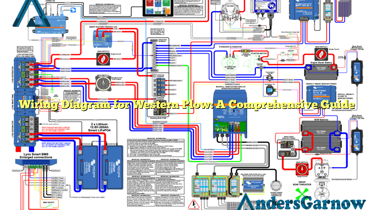
Hello and welcome to our comprehensive guide on the wiring diagram for Western plow systems. In this article, we will provide you with all the necessary information to understand and implement the wiring diagram for your Western plow. Whether you are a beginner or an experienced plow operator, this guide will help you navigate through the wiring process with ease.
Sub Heading 1: Understanding the Wiring Diagram
The wiring diagram for Western plows is a visual representation of the electrical connections required for the proper functioning of the plow system. It illustrates the different components and their interconnections, enabling you to understand how power flows through the system. By referring to the wiring diagram, you can easily troubleshoot any issues that may arise and make necessary repairs or modifications.
Sub Heading 2: Wiring Diagram Components
The wiring diagram for Western plows typically includes the following components:
| Component | Description |
|---|---|
| Battery | The power source for the plow system. |
| Control Module | The central control unit that manages the plow functions. |
| Control Harness | The wiring harness that connects the control module to the vehicle’s electrical system. |
| Motor Relay | The relay that controls the plow motor. |
| Power Cable | The cable that supplies power to the plow motor. |
| Solenoid | The device that controls the flow of hydraulic fluid to move the plow blade. |
| Lighting System | The wiring and lighting components for the plow’s headlights and auxiliary lights. |
Understanding the purpose and functionality of each component is crucial for correctly interpreting the wiring diagram.
Sub Heading 3: Benefits of the Wiring Diagram
The wiring diagram for Western plows offers several benefits:
- Easy Troubleshooting: With the wiring diagram, you can quickly identify and resolve any issues related to the electrical connections of your plow system.
- Efficient Repairs: If any component fails or needs replacement, the wiring diagram helps you understand how it fits into the overall system, making repairs faster and more efficient.
- Modification Flexibility: The wiring diagram allows you to customize your plow system by adding or removing components, ensuring compatibility and seamless integration.
Now that we have discussed the basics, let’s explore some alternative wiring diagrams for Western plows.
Sub Heading 4: Alternative Wiring Diagrams
While the standard wiring diagram for Western plows is widely used, there are alternative options available for specific plow models or customized setups. These alternative diagrams may vary in terms of component placement or additional features. It is essential to consult the specific wiring diagram provided by Western or seek professional assistance when implementing alternative configurations to ensure proper functionality and compatibility.
Sub Heading 5: Frequently Asked Questions (FAQ)
Q: Can I use the same wiring diagram for different Western plow models?
A: While some wiring connections may be similar, it is essential to refer to the specific wiring diagram provided by Western for each plow model. Differences in components or control systems may require specific wiring configurations.
Q: How can I identify the wiring diagram for my Western plow model?
A: The wiring diagram for your Western plow model can usually be found in the product manual or documentation provided by Western. Alternatively, you can contact Western’s customer support for assistance.
Conclusion
Mastering the wiring diagram for Western plows is crucial for the efficient operation, troubleshooting, and customization of your plow system. By understanding the components, their interconnections, and the available alternative diagrams, you can confidently navigate the wiring process. Remember to consult the specific wiring diagram provided by Western for your plow model and seek professional help if needed. Happy plowing!

